Clean hydrogen and carbon black, from (bio)methane.
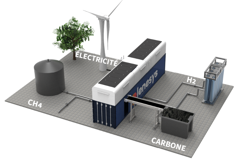
Modular, turnkey production units adapted to industrial operating requirements: the plasma arc splits methane into hydrogen and solid carbon, with no combustion and no direct CO₂.
The plasma arc splits methane directly into hydrogen and solid carbon. Unlike steam reforming, nothing is burned or oxidised.
(Bio)methane in — natural gas, biogas or flare gas, 1–6 barg.
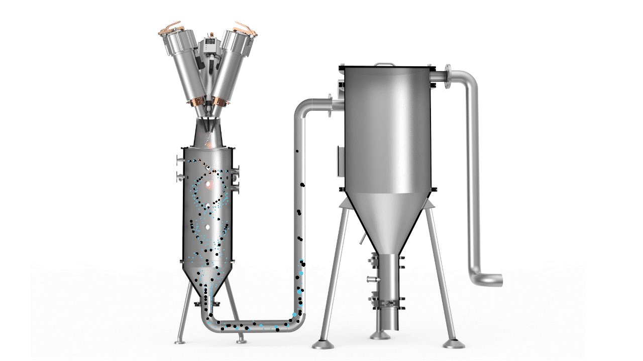
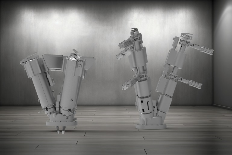
Three-phase plasma arc — above 3,000 °C; the arc’s motion mixes the gas, no oxygen involved.
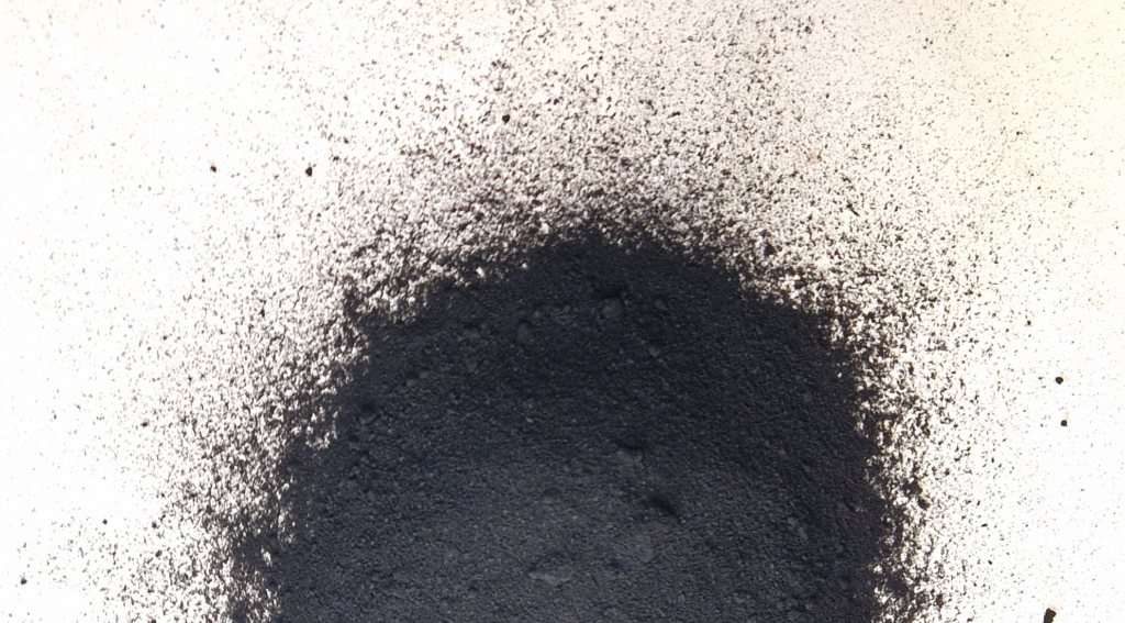
Hydrogen and solid carbon out — two valuable products, zero direct CO₂.
Technical features
The most cost-effective route to clean hydrogen.
Combined valuable products
Clean hydrogen and high-value solid carbon in a single process, without direct CO₂. Conventional routes rely on separate, energy-intensive processes for hydrogen production and carbon handling.
Competitive cost
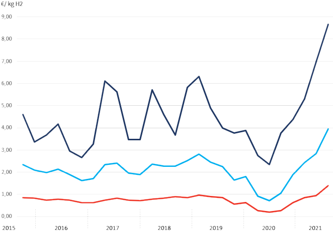
Low, stable production costs compared with conventional low-carbon hydrogen. Methane pyrolysis needs far less electrical energy per kilogram of hydrogen than water electrolysis, and the solid carbon co-product adds a revenue stream. Limited maintenance, economical consumables and no AC/DC rectifier keep the architecture simple.
Environmentally friendly
A methane pyrolysis process without combustion: no direct CO₂ at the point of hydrogen production. Carbon is recovered as a product rather than released as CO₂ — in line with industrial climate-neutrality objectives.
Low footprint
An optimised, pressurised design: operating at up to 6 barg reduces internal gas volumes and downstream equipment size, so the plant fits existing industrial sites where space is critical.
SEE THE REACTION
Methane in. Hydrogen and solid carbon out.
This animation illustrates the methane pyrolysis reaction inside the HyPlasma® reactor, resulting in hydrogen and solid carbon.
Specifications
Two sizes, side by side.
Specifications can be adapted to project-specific requirements.
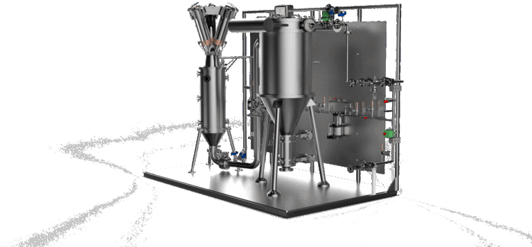
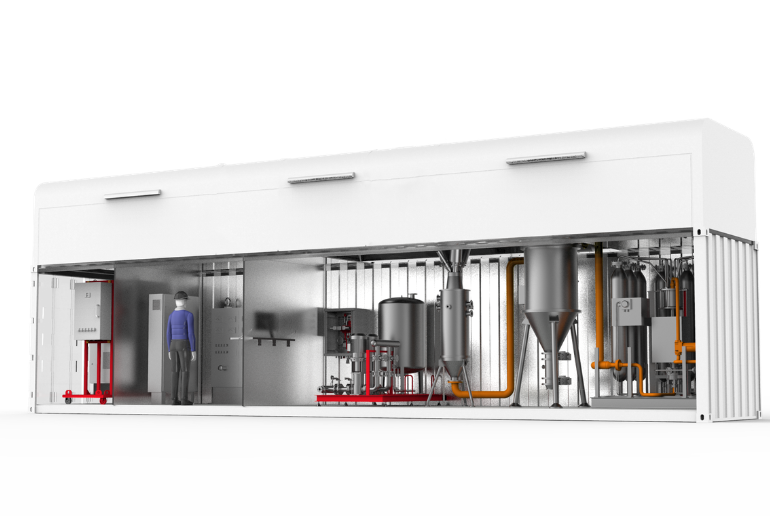
100 kW unit
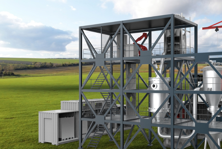
Containerised · 2 containers
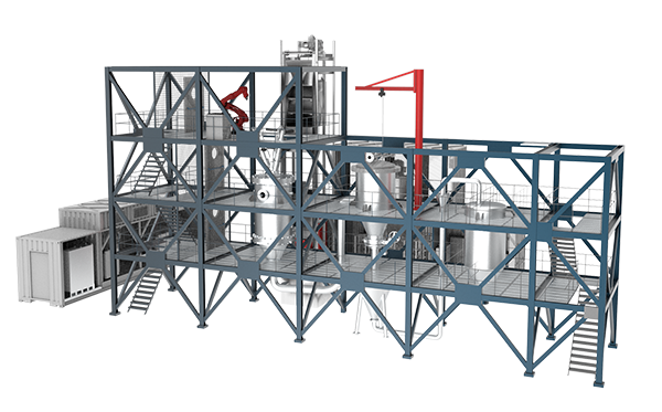
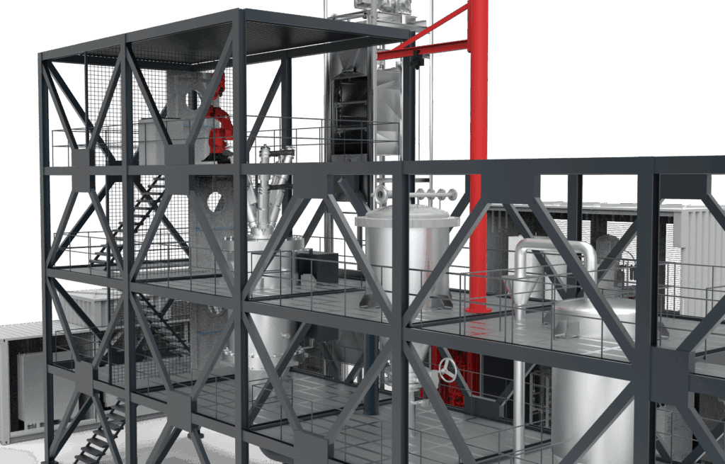
2 MW plant
Three-floor structure · ~100 m²
POWER
100 kW unit
30 – 100 kW
2 MW plant
2 MW
HYDROGEN OUTPUT
100 kW unit
7 kg/h59 t/year
2 MW plant
140 kg/h1,190 t/year
SOLID CARBON OUTPUT
100 kW unit
21 kg/h179 t/year
2 MW plant
380 kg/h3,570 t/year
OPERATING PRESSURE
100 kW unit
1 – 6 barg
2 MW plant
1 – 6 barg
GAS FEEDSTOCK
100 kW unit
Natural gas, biogas, flare gas…
2 MW plant
Natural gas, biogas, flare gas…
ELECTRICAL INPUT
100 kW unit
380/400 VAC · 3-phase · 50 Hz
2 MW plant
380/400 VAC · 3-phase · 3 MVA
CONSUMABLES
100 kW unit
Graphite electrodes · inert gas for start-up and cleaning
2 MW plant
Graphite electrodes · inert gas for start-up and cleaning
FOOTPRINT
100 kW unit
2 containersContainerised
2 MW plant
~100 m²3-floor structure
Highlighted rows are the two product outputs: hydrogen and solid carbon.